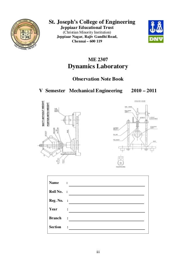
Dynamics Lab Manuals
ME 123L Engineering Dynamics Lab, Department of Mechanical Engineering ME 123L EGINEERING DYNAMICS LAB MANUAL Exp. Date Name of the Experiment Page No. Signature of No.
Vehicle dynamics Lab Manual. For PDF: Lab Manual of Vehicle Dynamics. Posted 24th July 2017 by kalp. Labels: Study Mate. ME 6512 Thermal Engineering lab II manual.pdf: File Size. Download File. ME 6511 Dynamics Of Machines lab.pdf: File Size: 334 kb: File Type: pdf: Download File. ME 6513 Metrology And Measurements.pdf: File Size: 1784 kb: File Type: pdf: Download File. Powered by Create your own unique website with customizable templates.
The Staff 1 FLYWHEEL AND AXLE SYSTEM 2 GYROSCOPE – TO MEASURE GYROSCOPE COUPLE 3 DETERMINATION OF SPEED AND SENSITIVITY OF WATT GOVERNOR 4 DETERMINATION OF SPEED AND SENSITIVITY OF PORTER GOVERNOR 5 DETERMINATION OF SPEED AND SENSITIVITY OF PORELL GOVERNOR DETERMINATION OF SPEED AND 6 SENSITIVITY OF HARTNELL GOVERNOR 7 a. CAM PROFILE DRAWING, MOTION CURVES 7 b. CAM JUMP PHENOMENON 8 SINGLE DEGREE OF FREEDOM – SPRING MASS SYSTEM. ME 123L Engineering Dynamics Lab, Department of Mechanical Engineering Ex. 03 DETERMINATION OF SPEED AND SENSITIVITY Date: FOR WATT GOVERNOR AIM To determine the speed and sensitivity of the Watt Governor APPARATUS REQUIRED 1.
Watt governor set up. Tachometer FORMULA 1. Height h = h0 – (x / 2) in m 2. Α = cos -1 (h / 2) in deg 3. Speed of Governor, N = √(895/h) rpm 4.
Angular velocity, ω = (2πN / 60) in rad/s 5. Force F = (w/g) X ω 2 X r (kg.f) KEYWORDS AND NOTATION Length of each unit, L in m Initial height of governor, h0 in m Initial radius of rotation r0 in m Radius of rotation, r in m Weight of each ball, w = 0.6 kg h - Sleeve lift in m N2-Maximum speed in rpm N1-Minimum speed in rpm N-Mean speed in rpm EXPERIMENTAL PROCEDURE 1. The watt governor assembly is mounted over the spindle. The motor is started and speed is adjusted.
Speed is measured with the help of tachometer. Due to this centrifugal force the sleeve will be rise, the speed and the sleeve height are noted. By using the formula the speed of the governor is calculated. The experiment is repeated at different speed and force. ME 123L Engineering Dynamics Lab, Department of Mechanical Engineering Ex. 04 DETERMINATION OF SPEED AND SENSITIVITY Date: FOR PROELL GOVERNOR AIM To determine the speed and sensitivity of the proell Governor.
APPARATUS REQUIRED 1. Proell governor. Weight FORMULA 1.

Height h = h0 – (x / 2) in m 2. Α = cos -1 (h / 2) in deg 3. Angular velocity, ω = (2πN / 60) in rad/s 4.
Speed of Governor, N = √ FM/BM x (m+M/m) x 895/h. Force F = (w/g) X ω 2 X r (kg.f) KEYWORDS AND NOTATION Length of each unit, L in m Initial height of governor, h0 in m Initial radius of rotation r0 in m Radius of rotation, r in m Weight of each ball, w = 0.6 kg h - Sleeve lift in m N2-Maximum speed in rpm N1-Minimum speed in rpm N-Mean speed in rpm SPECIFICATION FM/BM-proell link ratio =0.57.
M - Mass of the sleeve assembly=2.25kg m - Mass of the ball = 0.092 kg. EXPERIMENTAL PROCEDURE 1. The proell governor assemblys is mounted over the spindle. The motor is started and speed is adjusted. Speed is measured with the help of tachometer. ME 123L Engineering Dynamics Lab, Department of Mechanical Engineering Ex. 05 Date: DETERMINATION OF SPEED AND SENSITIVITY FOR PORTER GOVERNOR AIM To determine the speed and sensitivity of the porter governor.
APPARATUS REQUIRED 1. Porter governor. 1 Height h = h0 – (x / 2) in m 2. Α = cos -1 (h / 2) in deg 3. Angular velocity, ω = (2πN / 60) in rad/s 4.

Speed of Governor, N = √ FM/BM x (m+M/m) x 895/h. Force F = (w/g) X ω 2 X r (kg.f) KEYWORDS AND NOTATION Length of each unit, L in m Initial height of governor, h0 in m Initial radius of rotation r0 in m Radius of rotation, r in m Weight of each ball, w = 0.6 kg h - Sleeve lift in m N2-Maximum speed in rpm N1-Minimum speed in rpm N-Mean speed in rpm SPECIFICATION FM/BM = 0.49 M - mass of the sleeve assembly =2.25 kg m - mass of the each ball=0.225 kg EXPERIMENTAL PROCEDURE 1. The porter governor assembly is mounted over the spindle. The motor is started and speed is adjusted. Speed is measured with the help of tachometer. Due to this centrifugal force the sleeve will be rise, the speed and the sleeve height are noted.

Dynamics Lab Manual Pdf
By using the formula the speed of the governor is calculated. ME 123L Engineering Dynamics Lab, Department of Mechanical Engineering Ex. 06 Date: DETERMINATION OF SPEED AND SENSITIVITY FOR HART NELL GOVERNOR AIM To determine the speed and sensitivity of the porter governor. APPARATUS REQUIRED 1. Hartnell governor.
1 Height h = h0 – (x / 2) in m 2. Α = cos -1 (h / 2) in deg 3. Angular velocity, ω = (2πN / 60) in rad/s 4. Speed of Governor, N = √ FM/BM x (m+M/m) x 895/h. Force F = (w/g) X ω 2 X r (kg.f) KEYWORDS AND NOTATION Length of each unit, L in m Initial height of governor, h0 in m Initial radius of rotation r0 in m Radius of rotation, r in m Weight of each ball, w = 0.6 kg h - Sleeve lift in m N2-Maximum speed in rpm N1-Minimum speed in rpm N-Mean speed in rpm SPECIFICATION M - mass of the sleeve assembly =2.25 kg m - mass of the each ball=0.225 kg EXPERIMENTAL PROCEDURE 1.
The porter governor assembly is mounted over the spindle. The motor is started and speed is adjusted. Speed is measured with the help of tachometer.
Due to this centrifugal force the sleeve will be rise, the speed and the sleeve height are noted. By using the formula the speed of the governor is calculated. The experiment is repeated at different speed and force. ME 123L Engineering Dynamics Lab, Department of Mechanical Engineering Ex. 07 (a) Date: CAM STUDY MODEL AIM To draw the displacement diagram for various cam profile and roller follower APPARATUS REQUIRED 1) Experimental setup 2) Roller follower 3) Cams FORMULA 1. Displacement D = Change in lift lengh in mm 2. Velocity V = D / (1/360) in mm / sec 3.
Acceleration a = V / (1/360) in mm / sec 2 EXPERIMENTAL PROCEDURE 1. Taka a paper of size 40cm x 15cm 2. Use scale for x-axis as 1cm=100mm = 10ᵒ of rotation of cam. Take height of lift as10cm.
Plot displacement diagram for given cam profile. Fit graph paper on drum. Set ‘0 ᵒ’ as a starting point to lift. Give gradual rotation to complot displacement diagram on graph. Compare solution obtained by graphical. Do this for other cam profile and follower.
ME 123L Engineering Dynamics Lab, Department of Mechanical Engineering Ex. 08 Date: SINGLE DEGREE OF FREEDOM SYSTEM AIM To determine the natural frequency of spring mass system, damping factor and damping coefficient. APPARATUS REQUIRED 1.
Experimental Setup 2. Electronic timer 3.
Spring mass FORMULA Stiffness of spring, K = Gd 4 / 8D 3 n Natural frequency ωn = √(K/m) Damping frequency ωd = 2π / td Damping factor ξ = √1 – ( ωd / ωn) 2 Influence coefficient c = 2 X ξ X m X ωn KEYWORDS AND NOTATION Stiffness of spring, K Rigidity modulus, G = 0.8 X 10⁵ kg/mm2 Coil diameter, d = 20 mm Outer dia = 58 mm Mean diameter of coil, D = outer diameter – coil d iameter = 38 mm Number of turns, n Natural frequency ωn Mass attached, m in kg Damping frequency, ωd Time taken for one oscillation of mass, td Damping factor, ξ Damping coefficient, c. ME 123L Engineering Dynamics Lab, Department of Mechanical Engineering EXPERIMENTAL PROCEDURE 1. Keep one spring and mass only 2. Keep proximity switch at equilibrium position of masss 3.
Give 50 mm deflection to mass 4. Measure cycle time for vibration, td calculate ωd = 2π / td 5.
Calculate K = Gd 4 / 8D 3 n 6. Find natural frequency of spring for mass ‘m’, ωn = √(K/m) 7. Find damping factor ξ = √1 – ( ωd / ωn) 2 8. Do the above for other spring also. TABULATION Sl Weight Time taken for Damping Natural Damping Damping Added one oscillation frequen cy Frequency Factor coefficient No. Kg T ωd ωn ξ c Model Calculation.